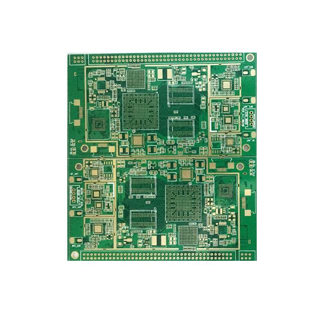
High Frequency PCB
High Frequency PCB | |
High-frequency PCBs generally provide a frequency range of 500MHz to 2 GHz, which can meet the needs of high-speed PCB design, microwave, radiofrequency and mobile applications. When the frequency is higher than 1 GHz, we can define it as high frequency. | |
PCB circuit board Files format: | Gerber, .pcb, .pcbdoc or .cam |
Printed circuit board Materical: | ARLON 85N ,Rogers 4350B,Rogers RO3010,ISOLA IS620,Rogers RO3006,Rogers RO3003,Rogers RO3001,Taconic TLC,Taconic TLX |
PCB board Surface Finishing: | ENIG/OSP/Gold Plating(Soft/hard) /HASL/Imm. Silver/IMM.Tin/Tin Plating/Carbon Ink/Selective /Imm.metal+OSP |
PCB board Cooper Thickness: | 0.5OZ-12OZ |
Printed circuit board Layer: | 1-24 Layer |
Printed circuit board thickness: | 0.25mm -10mm |
Min PCB Line Width/Spacing: | 0.075mm/0.065mm |
PCB board Min S/M Bridge: | 0.075mm |
Min PCB PTH Hole Size: | 0.15mm |
Min PCB Microvia Hole Size: | 0.1mm |
PCB board Outline Tolerance : | ±0.10mm |
PCB PTH Aspect Ratio : | 10/0.1 |
Impedance Control Single-ended/Differential: | ±10% |
PCB board Bow and Twist : | 0.75% |
Sample PCB Producing Leadtime | ||
PCB layer | Urgent (hour) | Normal (day) |
1 、2L | 24 | 4--5 |
4L | 48 | 5--7 |
6 、8L | 72 | 7--9 |
10 L and up | To be determined based on gerber file | |
The above lead time is based on: | 1.Material Available | |
2.All Engineering issues comfirmed | ||
PCB Mass Producing Leadtime | ||
PCB layer | Urgent (hour) | Normal (day) |
1 、2L | 24 | 4--5 |
4L | 48 | 5--7 |
6 、8L | 72 | 7--9 |
10 L and up | To be determined based on gerber file | |
The above lead time is based on: | 1.Material Available | |
| 2.All Engineering issues comfirmed | |


